
If you own a 3D printer you probably know the struggle. You are looking for a specific part to fix or mount something, but just cannot find one that fits. The first one is too big, the second one is missing a hole, the third one fails to print.
I’ve had that happen one too many times and decided to learn a new skill: Parametric 3D modeling
I’ve created this article to summarize the basic concepts of parametric 3D modeling, based on what I have learned by trial and error. This is not a definitive guide and may even contain bad practices that I have yet to figure out.
As always: It’s learning by doing and fixing what’s broken!
Table of Contents
Why FreeCAD?
Finding the right tool proved more challenging than expected. While many options offer affordable or free parametric 3D modeling, few meet my specific requirements:
- Offline Operation
- Free or one-time purchase licensing
- No propriatary cloud uploads
- Ability to export to 3MF or STL without restrictions
After a lot of research I finally settled on FreeCAD, even though some sources indicated that it had a steep learning curve.
FreeCAD Website: https://www.freecad.org/
Tutorial: Basic Hook
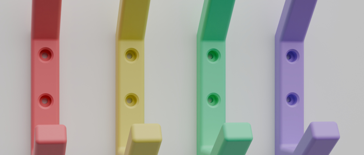
Starting FreeCAD for the first time can be overwhelming. There are lots of workbenches, each with a ton of features, options and settings. To keep it simple: You don’t need most of them to start modeling. Most of your time will be spent in the Parts Design workbench. For this demonstration we will model a basic hook with a screw hole.
Initial sketch
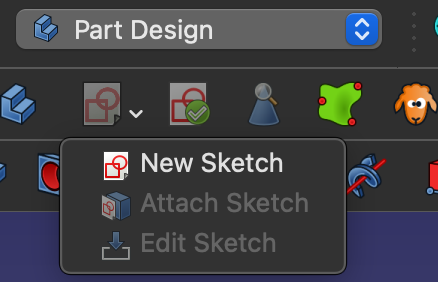
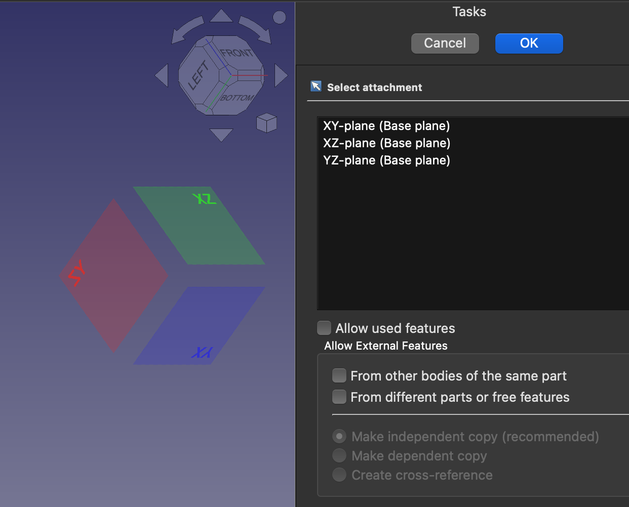
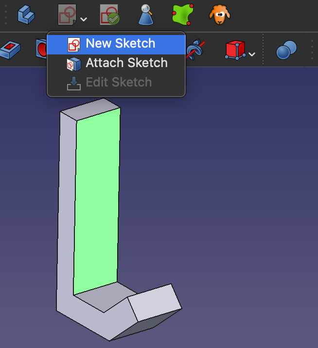
The creation of 3D models in FreeCAD starts with a 2D sketch that will be extruded or otherwise manipulated later. To create a sketch, use the New sketch option in the Parts Design workbench. FreeCAD will then ask which base plane the sketch should be attached to. This determines the orientation of your 3D model. Select the XY-Plane. This ensures that the final model lays on it’s side for easy printing.
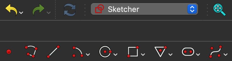
FreeCAD will automatically switch to the Sketcher workbench and present new features. We will use these to create a sketch. Use the Polyline tool to create the basic shape of the hook, viewed from it’s side, starting from the root point. Make sure that the shape starts and ends at the same position.
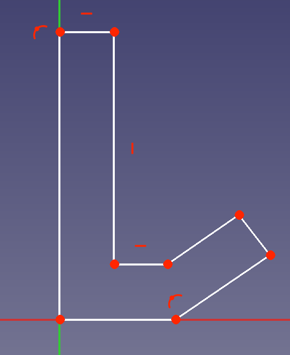
There is a very important concept in parametric 3D modeling that you need to understand:
Every feature in a sketch needs to be fully constrained, meaning that if your computer calculates the 3D model there is no ambiguity regarding the position, size, or orientation of any geometry, leaving zero degrees of freedom.
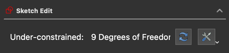
This means that every point, every line and every angle needs to either have a fixed position or be constrained by neighbouring values. Currently, our sketch is under-contrained as incidated by FreeCAD. The amount of degrees of freedom shows how many options there are to move the sketch.
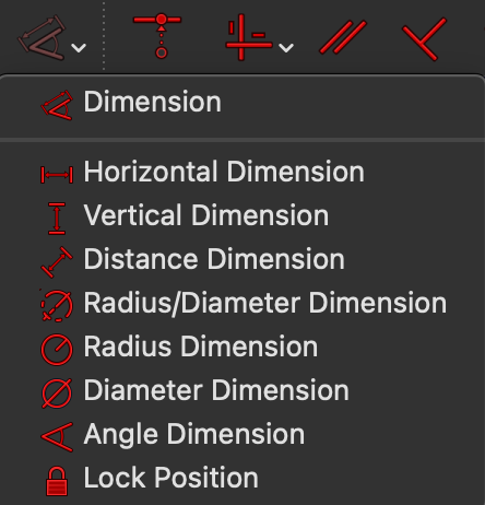
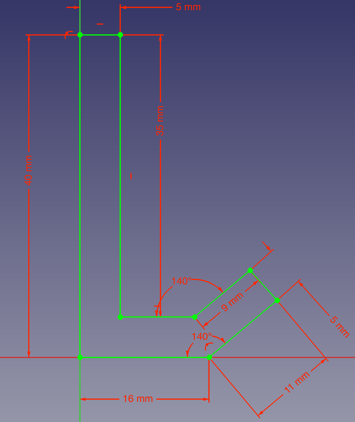
Let’s start constraining by first selecting the line that directly on the Y-axis and then selecting the Dimension Constraint or pressing (D) on the keyboard. This will create a constraint for the length of the line. Confirm with left-click and enter the size you want to set.
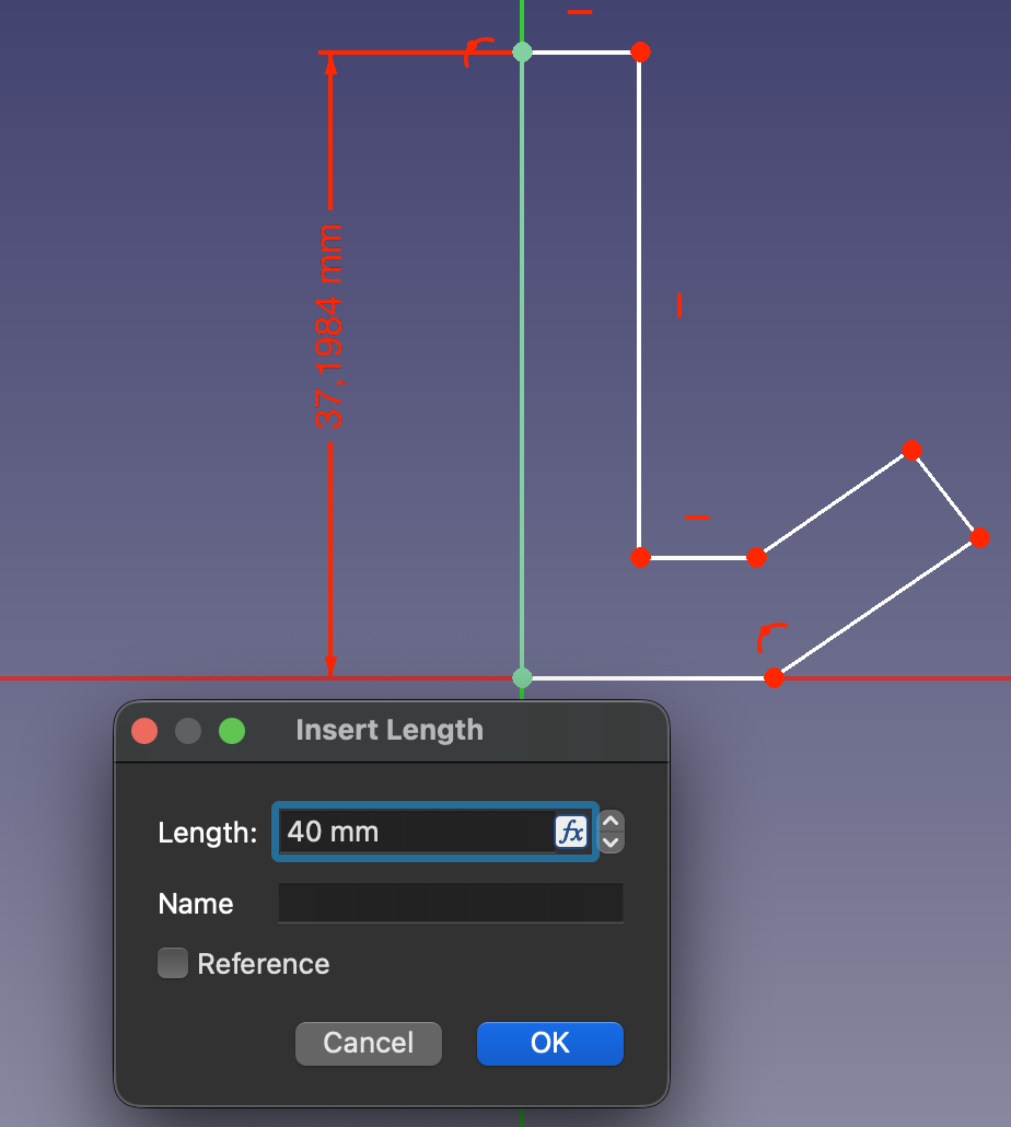
Now do the same for the other lines. You can use the dimensions from the screenshot below, or use your own. A light green line indicates a fully constrained part of the sketch, a white line is under-constrained.
For the angled part of your sketch there are multiple ways to use constraints. You can either continue to set lengths, which in turn creates a fixed angle for the part, or you can use an Angle constraint. To use an angle constraint select the two lines that will create the angle and then use the Angle Dimension constraint.
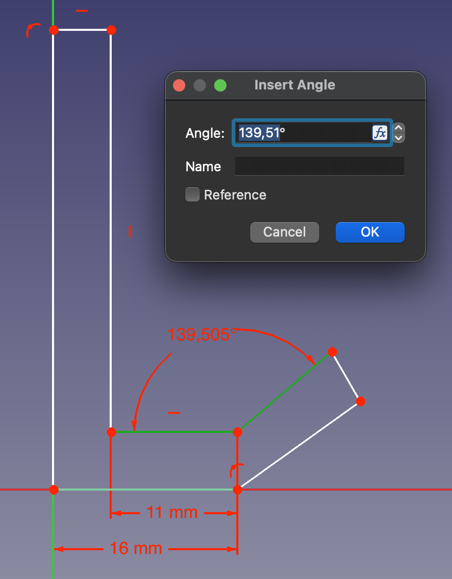
TIP: You can also use the Dimension constraint or press (D). FreeCAD will select the best possible constraint for you. Creating constraints can get messy. It takes some time to know which constraints work best for your sketch. The sketch from this tutorial only uses basic constraints to simplify the concept. It is possible to create a less messy sketch with more advanced constrains.
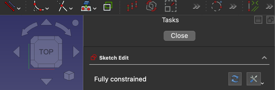
Once your sketch is fully constrained it turns bright green. You can then exit the Sketcher workbench with the Close button and return to the Parts Design workbench.
Padding the sketch
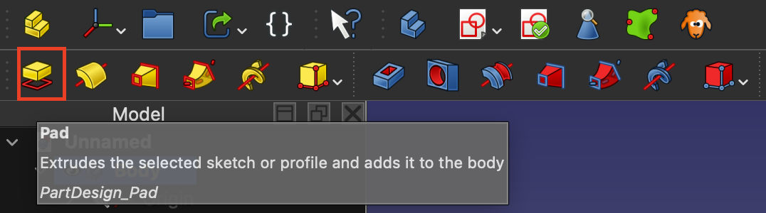
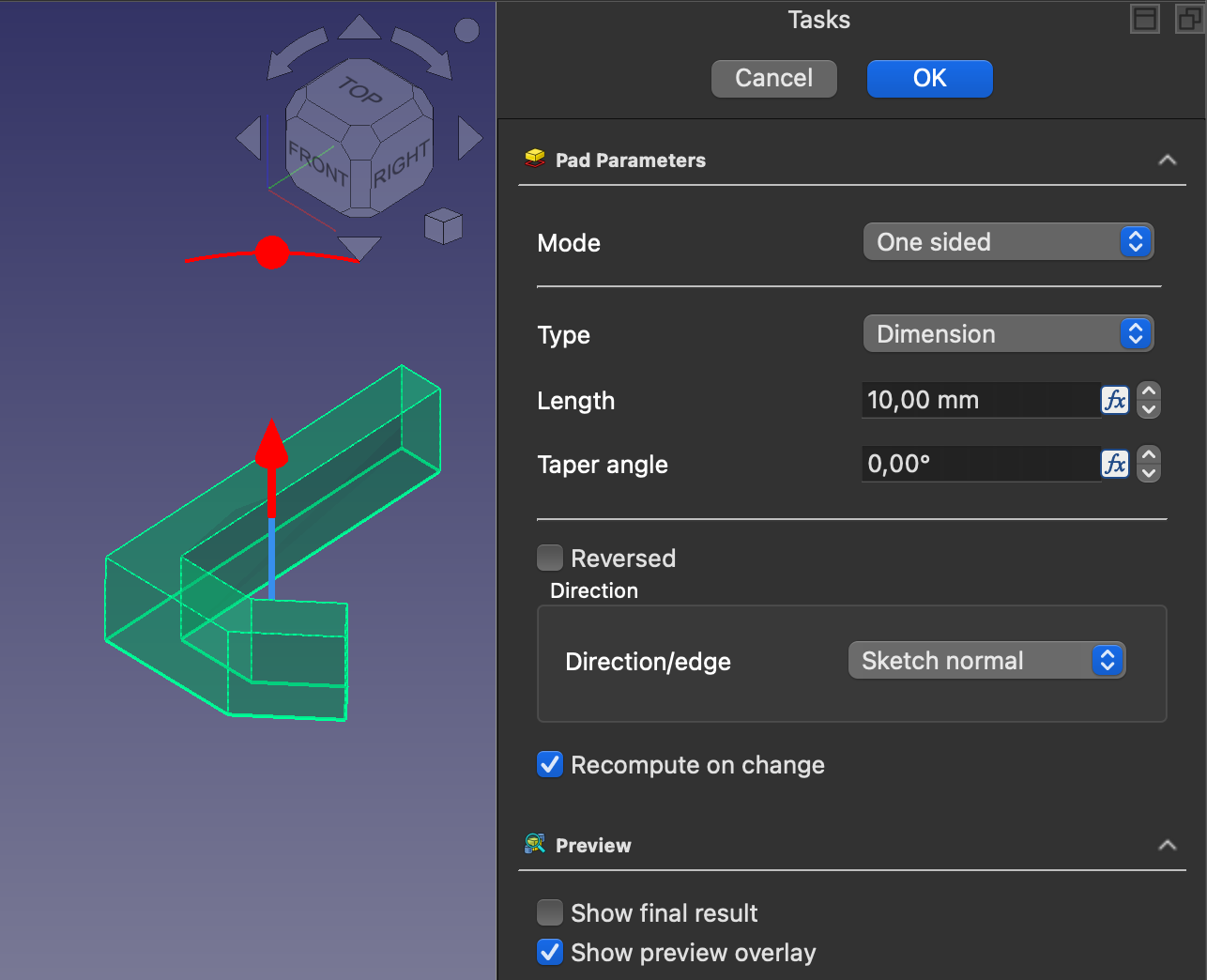
Back in the Parts Design workbench you should see your 2D sketch in the left menu. To create a 3D object from it, select the sketch and then the Pad option. You can set the length of the extrusion in the Pad parameters and confim your choice. This will create a 3D representation of the sketch.
Creating a hole
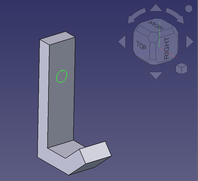
Our 3D object already has the basic shape of a hook but it still lacks a way to mount it. Select the highlighted face on your object and create a new sketch. The new sketch is now attached to the selected face, meaning that it is the plane we are working on.
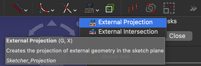
Next we need some references to position the sketch for the hole we are about to create. We can achive this by using External Projection. This feature allows us to reference geometry that is not part of our sketch and can be used to position features in releation to the object.
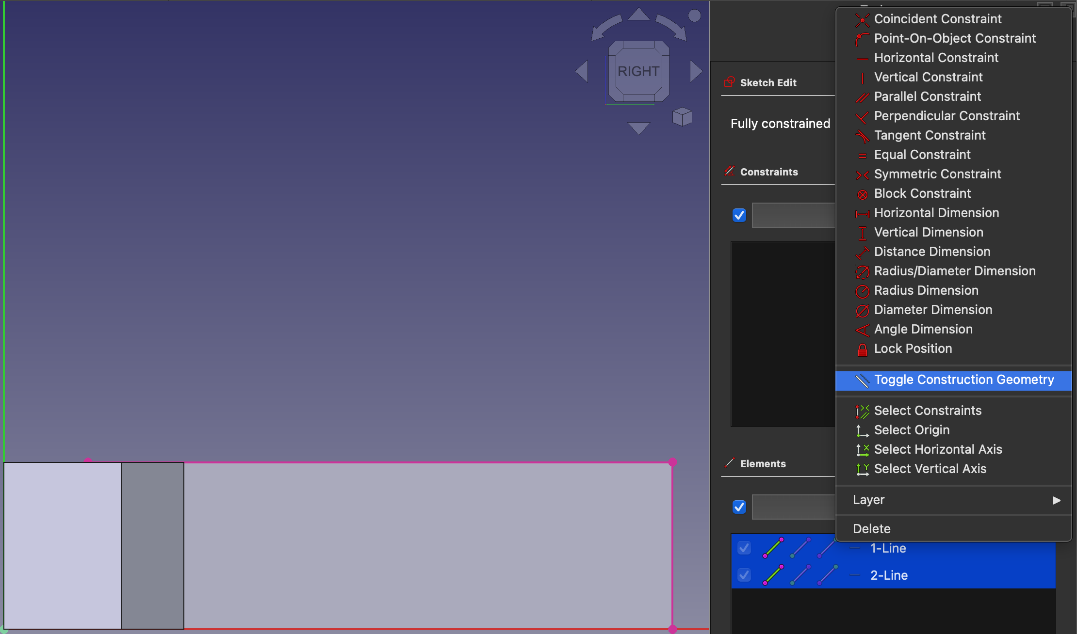
Use the External Projection feature to select the lines at the top and the right side. In the Elements menu on the right select both lines, right-click them and select Toogle construction geometry. This ensures that the referenced lines will not be considered part of the new sketch and only function as references. The reference lines will turn into dotted lines.
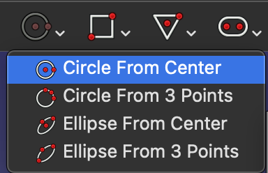
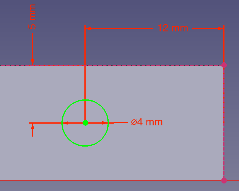
Now we can create a mounting hole using the Circle from Center feature and constrain the position of the middle point in releation to the reference lines, using the Dimension constraint. Once the hole sketch turns green, return to the Parts Design workbench.
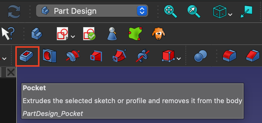
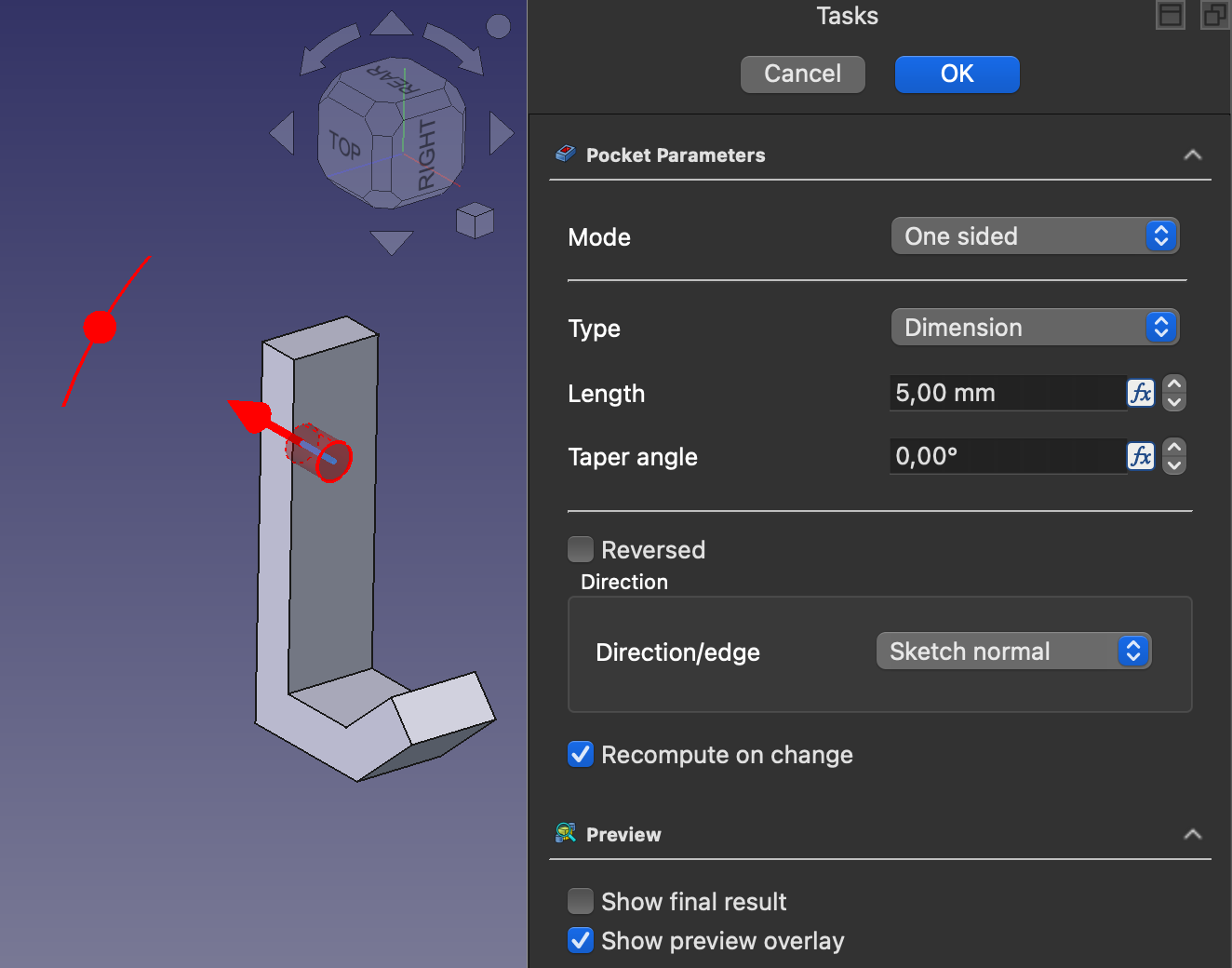
With the sketch selected in the menu on the left, use the Pocket feature to create a hole.
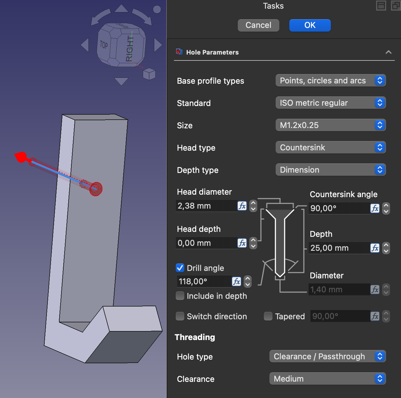
NOTE: You can also use the Hole feature. Keep in mind that it ignores the hole diameter you set in the sketch and instead has it’s own set of parameters that you need to configure. The Hole feature works great if you want to use specific screw types or need a modeled thread.
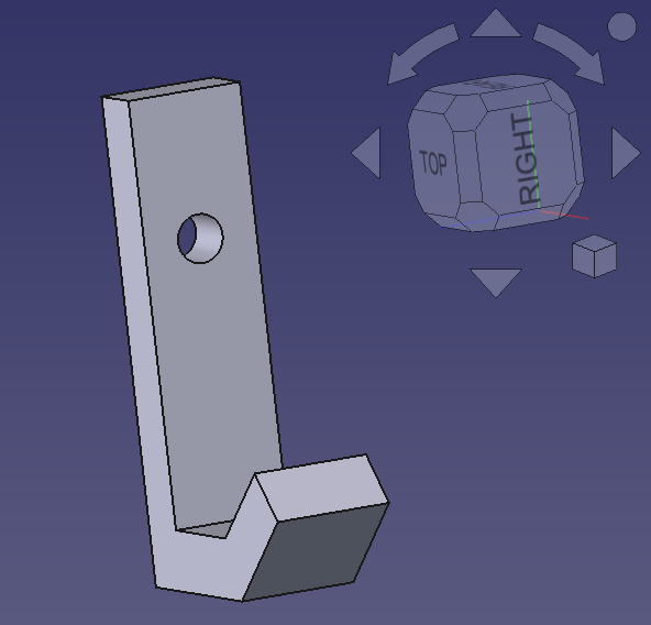
Regardless of the feature you applied, you should now have a fully modeled hook with a mounting hole.
Make it look professional
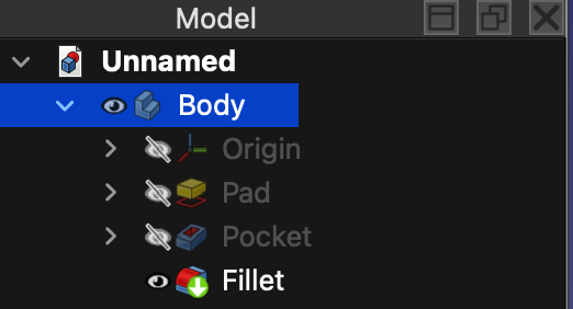
The hook in it’s current form is fully functional but still lacks the visual appeal that you may want. To fix this we can add a fillet or chamfer to the edges of the model.
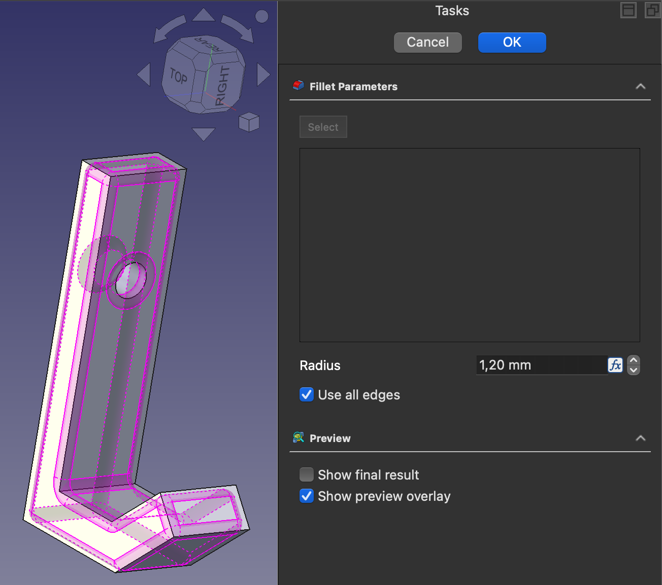
Open the Fillet or Chamfer feature and select all faces or edges that you want to edit. If you want to add all edges to the selection, select the Use all edges option. Make sure to set a radius that works for your model. If the radius is to big, the selection will turn red. Confirm the task once you are happy with the preview.
Note: Fillets and Chamfers should be the very last step in your model creation process. Editing a model after adding these features may cause issues with external references. If you need to change something it is recommended to remove these features first.
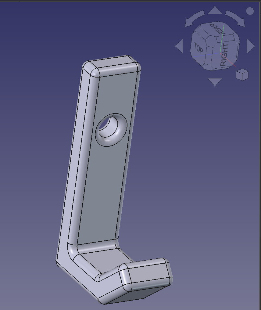
Congratulations! You have sucessfully created your first parametric 3D model!
Export your model
To export your model, select the entire body in the model menu. Go to File –> Export to export the model. For 3D printing, choose 3MF or STL as the file type.
What’s next?
Now that you know the basics of FreeCAD it is up to you to decide what you want to create. Keep in mind that this article barely scratches the surface of what is possible. Check out the detailed FreeCAD wiki for more information!
FreeCAD Wiki: https://wiki.freecad.org/Main_Page